Step 1 Vision Step 2 Procurement Step 3 Support Step 4 Refurb Step 5 Poles Step 6 Hole !! LET there be LIGHT !! The most frequent question I receive from visitors to our website and playing fields is, "Did you put up those lights yourself ? How ?" So, while I have opportunity, I will show how, in a reduced fashion, as I am adding a permanent light pole on the newly christened CC Field (Carroll Construction). Step 1 - The Vision Return to Top How do you end up with 2 million lumens of light in your back yard ? For me it all started with a Christmas request. My nephews come over to play football almost every Saturday, before or after the Ohio State game. With the time change in the fall, darkness terminated more games than not. Levi casually said after one of these times, "Man, would it be nice to have lights to flip on and keep playing." That got me searching, planning and scheming. Step 2 - Light Procurement Return to Top Step 1 in this process was to find the necessary light fixtures. Originally the back yard was lighted by 24 1500 watt halogens I purchased via ebay from a dirt track in Texas. I paid $5 each for 60 of them and they were a mess. I was able to refurbish them into 30 working units. The remnants of these 24 now light CC field, being replaced. The downside to these units is the amperage they draw. Each light draws 6.25 amps, resulting in a total draw of 150 amps for the backyard alone. I had to make sure every thing else in the house was off that 1st year. Still, the lights frequently shut off when the main house breaker popped due to a dryer or stove being turned on by my lovely wife. Each of the halogens put off 33,000 lumens, equal to 33-100 watt light bulbs, or 3-500 watt flood lights. These lights also illumine our full basketball court - with 9 being used for that. The second stage solution was metal halide lights. Metal halides use a strong electro magnet to increase the power of the lights and reduce the amperage required. For example, a 1000 watt metal halide puts off 110,000 lumens, equal to 110-100 watt light bulbs, but at 240 volts only uses 4.25 amps. The same lumens in halogen lighting would draw 21 amps, and a whopping 110 amps for incandescent (normal) light bulbs. The gotcha on metal halides is the cost, with 1K watters selling for an average of $400 each. All big stadiums are illuminated with these lights, usually 1500 watters. I obviously could not spend $400 for 24, and I got a real break. My brother Jim helped refurbish the Dayton courthouse, and brought home the lens portion of 6 of these units. I found the ballasts on ebay over the course of a winter for about $200 and made weather proof ballast boxes out of Army ammo boxes. These 6 units replaced 1/2 of the halogens - 1 entire side. Then I hit the jackpot. A Polaris like shopping mall in Chippewah Falls, WI went under, and the contractor who did the dismantling listed the 70 parking lot lights on ebay. He was adamant all be sold at once and had several folks back out at the $ 10,000 mark after ebay auctions. His wife got tired of the units being stored in the garage (they are huge). She said get 'em out. Best yet, they were military spec Wide Lites, the Cadillac of lighting, selling new for $800 each new. I made a deal and purchased all 70 for $25 each. From the desolate waste lands of Wisconsin the lights made their way to illumine our backyard stadium. I replaced all of the lights on the 6 poles in the backyard in spring #2, modifying the support beams to facilitate the new mounting pieces of the Wide Lites (pipe based). As time has passed I have also replaced all of the halogens around the basketball court with metal halides, making the supporting brackets on the 5 closest to CC field capable of being rotated, so they can illumine either the bball court or the wiffleball field. I also devised a lowering mechanism so the bulbs can be replaced from the ground, rather than 20 feet up.
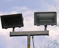
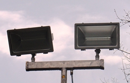
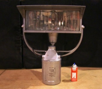
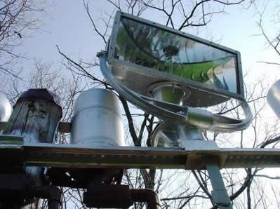
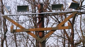
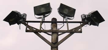
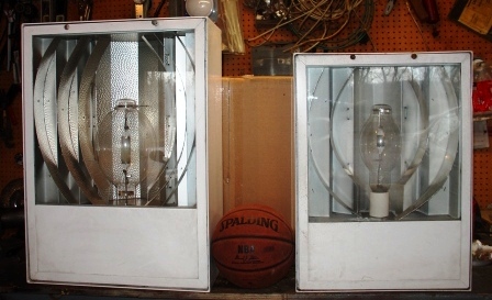
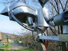
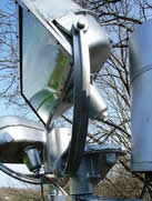
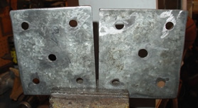
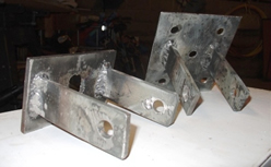
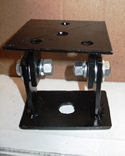
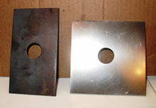
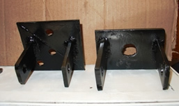
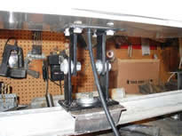
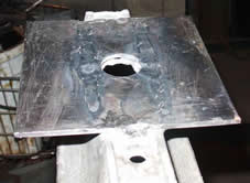
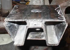
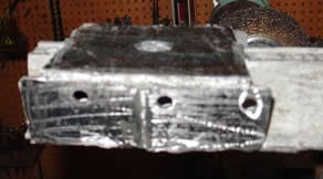
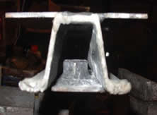
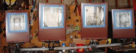
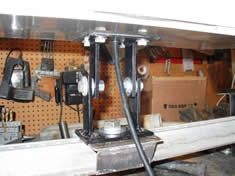
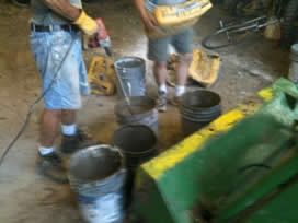
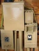
I sold the remaining 35 for an average of $150 each, completely paying for the cost of the entire lighting project (not including the hundreds of hours I spent fabricating). Unfortunately, that left me with no metal halides to illumine the other half of TLC Yards. By chance, after putting ads into Craig's list for over a year, someone called with 11 lights. Although they do not match the voltage I have, and were meant to be mounted pointing down, I am modifying them to work for this new application. The lights cost me $175. I ended up with 4-1000 watters and 7-400 watters. Their size is shown below with a basketball for size reference, with the 1k watt light on the left. Step 3 - Support Fabrication Return to Top The original lights are slip fitters, meaning a pivot point on the ballast slips over a 2" pipe. The angle of the lens is adjustable via 2 bolts and 2 set screws fix the female end of the ballast fitting on the pipe. I welded 24-5 inch pipe pieces while perched on a 30' ladder or scaffolding. I used a pulley attached to each telephone pole top to hoist my Lincoln Weld Pack 150 up, via a rope fixed to my tractor. This was accomplished in 1 spring and early summer (pictures above). Due to the weight of the lights (80 lbs each versus 2 for the halogens) the pole cross and down supports were strengthened significantly to bear the extra strain. The bball court lights were attached to telescoping poles, with the ballasts mounted remotely at the bottom of the support poles. In this manner only the lens needs to be hoisted when light bulb replacement is required (see pictures above).. For this new project, new brackets had to be fabricated. A flat plate for fixture on the bottom of the lights was cut (A). Down supports were cut and welded to this plate (B). This was repeated and the 2 halves connected by grade 8 1/2 " bolts so the angle of the lights can be adjusted (C). A - flat plate attaching to light B - down & up supports to plates C - completed bracket 4 of these brackets were created, with 3 hours fabrication time for each being required. D - platform piece top bracket on left, bottom right assembled bracket The 4 light brackets provide up and down angle adjustment via 1/2" bolts in the center of the brackets. The cross beam (E) is a galvanized road sign support obtained from an industrial supply vendor. A platform piece (D) is then welded to the top and bottom of the cross beam. A 3/4" bolt connects the entire bracket (E) to the cross beam, allowing left and right adjustment. The bracket is connected to the light fixture via 4 or 5-3/8" bolts. D- top and bottom cross beam light platform completed platform The brackets are next mounted to the cross beam. The locations of the light placements are determined. Then the proper holes on the cross beam are torched to facilitate the 3/4" bolts (F) to connect the light brackets to the beam. The platform flat pieces are then welded to the cross beam and side pieces welded on to increase the structural rigidity of the beam (G). F & G - finished platform E - cross beam with light platform H - nut welded in A 1" nut is welded to a washer and then the whole welded to the bottom flat plates (H). These bottom assemblies are then lined up with the top plates and welded to the bottom of the cross beam. The main brackets for attaching the cross beam to the telephone pole is then centered and welded to the cross beam (I). Lastly, attachment points for the down angle supports to the main light pole are cut, tapped for a bolt hole and welded into place at the ends of the beam. I - main cross beam support after welding I - before bolting to pole The cross beam including the pole mounting brackets, 4 platforms and down supports took a total of 12 hours to fabricate, clean and paint.
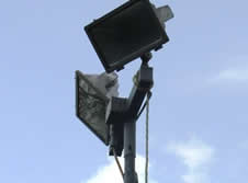
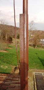
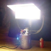
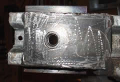
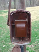
Step 4 - Light Refurbishment Return to Top Most of the lights procured were in need of refurbishment. For example, this last set was nearly 25 years old. The weather proof seals were dry rotted, allowing water and insects to penetrate the case. The wiring was setup for 3 phase 208V and the interior lens was coated with oil and dust (when the ignitor / capacitor goes south it emits oil). Most importantly, my lovely wife said she would not tolerate hideous huge white boxes in the front yard. So, I first removed the weatherproof seal and the previous wiring harnesses. Then the inside of the lights were cleaned with a strong degreaser and then cleaned again. Strong contact cement was applied to the inside edge of the lights and industrial weather stripping installed around the inside perimeter of the light fixture. A new wiring harness was crafted and installed with the proper connections and a new extension for power wired in. New metal halide bulbs were installed and the latch mechanism upgraded. The lights were then tested to ensure they functioned properly. The mounting brackets were then affixed to the lights and the housings closed and sealed with caulking as an added precaution. The lights were remounted on the cross bar, hooked up to a power source and turned on to ensure one last time all functioned, and the mounting brackets worked as designed. The lights were then painted the color chosen by my decorator, allowed to dry and demounted from the cross beam. The cross beam was then cleaned and primered in preparation for mounting on the pole and attachment of the down supports. lights refurbished, painted and mounted for final check bracket assembly installed Step 5 - Light Pole Preparation Return to Top
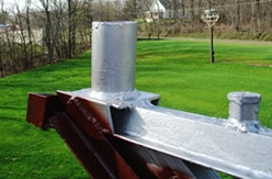
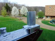
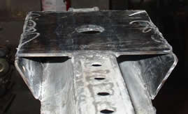
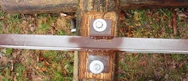
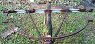
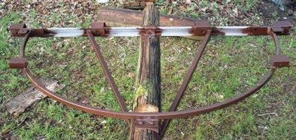
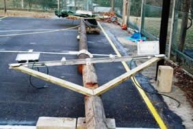
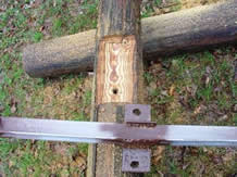
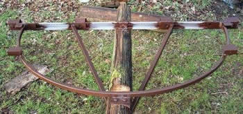
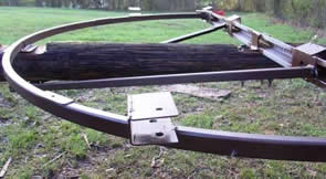
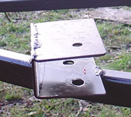
The 6 original light poles were obtained when South Central Electric replaced the poles carrying electric service up our road. The poles were 35' long and I cut them to be 25-28' in length. The new pole will be 30' long as the lights need to be slightly higher to better cover the field proportionately. The pole is first notched with a chain saw where the cross beam will attach to the pole (J). Holes are then drilled for the main cross beam supports and the cross beam is attached to the pole (K) via 2-5/8" x 12" bolts. J - notch for cross beam K - cross beam bolted to pole J- notches for down supports K - assembled supports including ladder post The down angle supports are then fabricated and attached to the cross beam with 3/8" bolts. The supports (both right and left) are adjusted to the middle of the pole and the position is marked. This spot is then notched with a chain saw and a hole drilled which will be use to secure both supports to the pole via a 12" x 5/8" bolt (L). The top end of the left and right supports are then welded into their fixed positions (M). L- notches for down supports M & N - cross beam supports & down supports welded into place Angle iron brackets are then welded onto the left and right down support members at the same position on each arm (N). These will be used to secure a 2" x 4" x 8' long horizontal beam for the ladder to rest on when "repairs in the air" are required (O). O - ladder beam support brackets Bolts are secured through the angle iron pieces to the 2" x 4" ladder support beam and the cross beam and its elements are now ready to be painted in final preparation for the light pole to be buried upright in the ground. Step 6 - Pole in the Hole Return to Top Holes for the light poles were dug to 5' in depth. To ease the process of standing the poles upright, a slide was excavated going down into the hole so poles could slide down the ramp as they were being lifted upright. The poles were then placed with the down end at the ramp and the light end sitting on blocks several feet off the ground (so the tractor could get under to lift). Two upright stands were fabricated for the bucket of the tractor. After maneuvering under the pole, with the pole between and chained loosely to the uprights on the tractor bucket, the tractor was driven forward slowly and the bucket raised.
This was a harrowing experience as the weight and leverage of the poles, combined with the relatively short reach of the tractor bucket, caused the back end of the tractor to get very tipsy. There was a break over point where I had to throttle up and just get the pole in the hole. Once the poles were resting on the gravel and concrete base at the bottom of the holes, the tractor could easily keep them straight. Approximately 10-80 lb bags of Quickcrete were mixed and dumped into each pole hole after the poles were plumbed straight. 2" x 4" braces were used to secure the poles in the plumb position and a day later the surrounding earth was returned to the hole and compacted. This results in a 1/2 ton anchor of concrete for each pole.
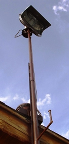
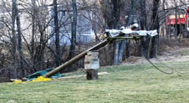
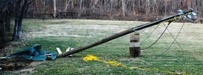
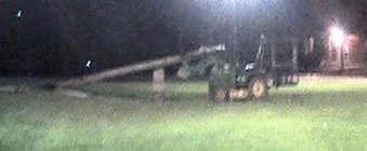
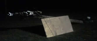
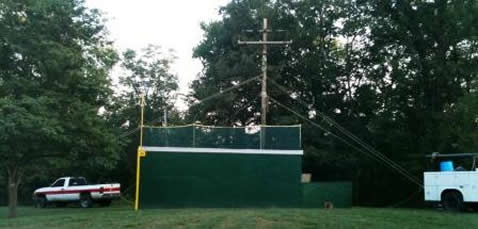
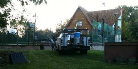
For the most recent pole, on Carroll Construction field (in the front yard), a different plan was executed. To reduce the chance of lights shining in the batter's eyes, Levi convinced me to use a much taller pole than was used in the back yard. The average height of poles in the backyard is 25 feet, with 5 feet being buried in the ground. We chose a 40 foot tall pole for the new install. This pole was simply too big and heavy for my tractor to rotate into the hole by itself. We asked our neighbor - Dave Britt, who erects towers for a living (convenient, huh ?) to give us a hand. Dave is a great Christian guy and his family is tops. So Dave brought his big truck over and attached his electric capstan to the hitch on the back (P). A thick rope was attached to the bumper of Dave's truck then run through a double block on the cross beam of the pole to the trunk of the Plinko tree and then back through the block to the capstan. Guide ropes were attached around the upper middle of the pole to both the bumper of my truck, and a huge ash tree on the side Dave's truck was on (Q). These guy ropes had figure 8's for Levi and I to pull the slack out of as the pole was raised. P - capstan on Dave's truck Q - the whole setup, trucks, blocks, Plinko tree Unfortunately, it had been so long since I erected my last pole that I forgot the trick I had learned. The green monster made the angles on this lift difficult. Normally I place a 1" sheet of plywood in the hole so the lifting pole will contact it and slide down into the hole. I forgot to do that this time and instead we pulled the pole nearly 2 feet through the ground (at 1' deep) to the green monster (very heavy pole). Then we realized what we did and set the pole back down, undid all the tackling and placed the boards in the hole, rebuckled and attempted the lift again ... with no more success. The pole was just too heavy at the bottom with the angles we had. So, I climbed on the tractor and lifted the top end of the pole up, sliding the bucket down the pole as the capstan raised the pole. It is a disturbing feeling to have 1,000 lbs of pole directly above your head as your tractor gets light in the back end and the wheels come off the ground.
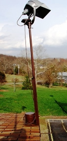
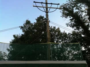
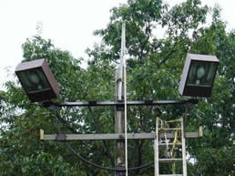
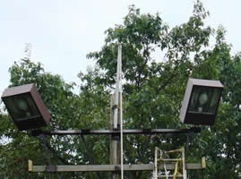
But after the tipping point the bottom of the pole plunged into the hole and we were home free. Our first thoughts were..."man, this pole is tall !" Dave Britt hard at work on the ropes A 40' tall pole with the ropes still rigged
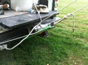
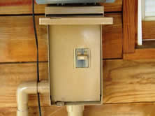
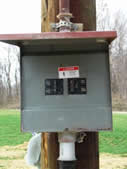
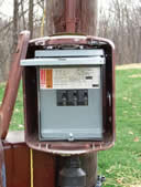
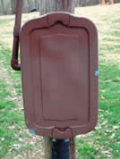
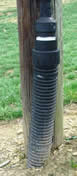
To secure this pole in the hole we mixed up 14 80 lb bags of Quickcrete, in record time, I might add. Using my 1/2" paddle drill we mixed up 16 5 gallon buckets of concrete and had them in the hole in less than 1 hour (about 1,500 lbs of concrete). Dave left his truck and tackling overnight so we did not need to secure the pole plumb with boards. Step 7 - Light Mounting and Electrical Connections Return to Top After the concrete in the hole has cured sufficiently the process of final wiring and adjustment of the lights to their proper position is begun. Although this seems straight forward, lights weighing 80 lbs each and extremely awkward make for an exciting trip wrestled up a ladder 25', especially when the lights need to be lifted overhead and slipped over a fitting or held while bolts are positioned and tightened, at the end of the ladder march. On this latest pole Levi and I had a revelation when we went out to set the ladder up to begin the light mounting process. My 34' extension ladder did not reach the cross beam of the new pole. Oops and ouch. I have gotten over my fear of heights - our house type demanded I do so, but this was too much for me. I have a 38' extension ladder but there is no way I intended to wrestle with 80 lbs of light perched at the tippy top of a 38' ladder. So we erected 2-5' sections of scaffolding and placed the 34' ladder on top of the scaffolding. For those OSHA minded individuals I always work with the ladder tied off to the pole in 2 places, with a full harness connected to both the ladder and the pole. The only way I suffer injury due to falling is if the pole breaks below the ladder apex point. Still, 40' up is 40' up. My experience has been, and Levi confirms this, it is easy to say, "You should do this or that", from the ground. Levi did so and I challenged him to just climb the ladder. He got up about 1/2 way (~ 30') and could go no farther. I guess when I pass on and a bulb goes out he will just have to sell the place. One by one the lights are attached to a rope running through a pulley attached to an extended metal pole bolted to the top of the light pole. The 2nd end of the rope is then tied to the tractor. When the tractor is driven driven away from the pole the light is lifted to above the cross beam. We made some modifications to our pulley and beam system for the front field pole and have been pleasantly surprised by how easily the lights have been moutned. One by one the lights are attached to a rope running through a pulley attached to an extended metal pole bolted to the top of the light pole. The 2nd end of the rope is then tied to the tractor. When the tractor is driven driven away from the pole the light is lifted to above the cross beam. In this manner slack can then be gathered when the tractor is reversed back to the pole, and the light wrestled into its permanent position, with no death defying maneuver required (I kind of like it that way). After all 4 lights are mounted on their cross beam platforms, the individual light power cords are congregated into a single weatherproof junction box mounted at the cross beam level (P). A single wire (10 gauge - 30 amp) of the underground burial type is mounted on the pole in pvc conduit (Q). This wire is connected to a second junction box at 4' in height at the base of the pole (R). For this new pole this junction box contains a 30 amp NEMA connector that can be plugged and unplugged. For this pole the power cord is not buried but ran overhead from the barn to the pole. The line is shielded by both flexible conduit and a thick rubber jacket encapsulating the conduit. All power lines to the backyard poles are buried. Each pole has its own weatherproof junction box, mounted inside a hard plastic protective case (S). The lights on each pole can be turned on and off at the pole, or via a master switch at the pole closest to the house on each side, with a breaker for each pole. Additionally, there are 2 master breakers on the porch for the light poles on each side of the yard (t). These are typically used to turn the lights on and the breakers at the pole left in the on position. T - main breakers road side T - woods side S - 1st pole box S - 4th pole box
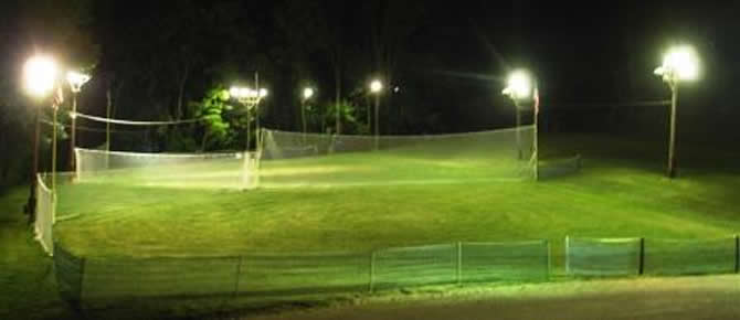
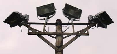
Number 2 copper wire was run from the main house box to the master junction boxes on the back porch. 2 aught aluminum wire (300 feet) was run from the master junction boxes to the 1st pole (100 amp). Number 6 copper wire was run (80 amp) from the 1st pole to the 2nd pole and Number 8 copper wire (55 amp) was ran from the 2nd pole to the final on each leg. The wiring is oversized but I wanted to be safe, and the original light array used the halogens, which pull more than double what the metal halides pull. All wire is direct burial, the connections on both ends are waterproof, of my own design, and kind of nifty. At least I think so. My nephews assisted in the digging of the 600' of trench, pulling of the wire, and re-filling of the hole (all in one very long day). For additional safety, each pole has its own 8' ground rod, connected to both the pole and junction box on that pole. junction boxes inside junction box inside conduit inside with plastic case plastic case fittings to waterproof Step 8 - Finished Results Return to Top These speak for themselves, as the pictures on this site attest. Literally 1'000's of hours of Wiffle Ball, football, golf, frisbee, soccer and even the odd paint ball game have been played in the wee hours of the morning in our backyard stadium. Now if I could only find reasonable artificial turf....
|
|||||||||||||